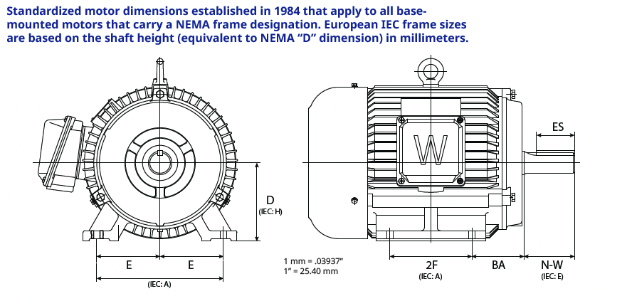
Electric motors are essential components in various industrial applications, from manufacturing to HVAC systems. A motor’s physical dimensions and mounting configurations, designated by standardized Frame Numbers, ensure compatibility and ease of replacement across different manufacturers. The National Electrical Manufacturers Association (NEMA) set these standard frame numbers in the USA. Internationally, the International Electrotechnical Commission (IEC) designates standardized sizes. Understanding these frame numbers is crucial for engineers, maintenance personnel, and procurement specialists. Let’s delve into the specific meanings behind NEMA and IEC frame numbers.
NEMA vs. IEC Frames
While NEMA and IEC frame numbers serve the same purpose, their specific measurements and standards differ. Here’s a comparison:
- Measurement Systems: NEMA uses imperial measurements (inches), whereas IEC uses metric measurements (millimeters).
- Standardization: Both systems ensure interchangeability, but specific dimensions and tolerances vary.
- Geographic Preference: NEMA standards are primarily used in North America, while IEC standards are prevalent internationally.

NEMA Frame Numbers
Here’s a breakdown of what NEMA frame numbers signify:
- Frame Size and Shaft Height: The first two or three digits in a NEMA frame number indicate the “D” dimension or shaft height in inches. To obtain it, divide the first two numbers by 4. For example, a NEMA 324T frame motor has a shaft height of 32/4 or 8 inches.
- Mounting and Shaft Dimensions: The letter suffix in the frame number provides additional information about the mounting and shaft dimensions.
- The third digit in the integral T frame size number is the NEMA code for the distance between the center lines of the motor feet mounting bolt holes from the front to back. For example, the distance between the center lines of the mounting bolt holes in the feet of a 143T frame is 3.00 inches, while the 145T frame is 5.00 inches.
- The last letter(s) designates the series of dimensions to adhere to. NEMA was founded in 1926 and developed its original standardization system, which lasted nearly forty years. The “U” frame designation was introduced in 1952 and superseded in 1964 by the “T” frame system. All three eras in frame sizing have very similar dimensions in most aspects; they vary in critical ways. The “T” frame has remained the standard for NEMA frame manufacturing to the present day.
- In addition to the U or T frame distinctions, additional callouts like C, D, Z, etc., provide more specific information about the motor’s mounting configuration and intended use. Here is a description of what these callouts represent:
- C Frame refers to a motor designed for C-face mounting with a rigid base that is commonly used in pump and fan applications.
- D Frame: Similar to TC frames but designed for use with a drip-proof enclosure.
- Z Frame: Typically equates to the shaft on the motor, which will have a nonstandard dimension. Could designate a longer shaft, thicker in diameter, threaded, longer keyway, etc.
- Y Frame: Designates that the motor’s mounting will be nonstandard to normal NEMA products and custom to an application, such as a special C face or spline shaft integral to the application.
- Additional Dimensions: Other critical dimensions designated by the NEMA frame number include:
- Shaft Diameter (U): The diameter of the motor shaft.
- Shaft Length (N-W): The exposed length of the motor shaft
- Side to Center on Mounting Holes (E): The length between the centerline of a mounting laterally to the center of the motor
- The distance from the front of the mounting feet to the start of the exposed shaft (BA) is critical in mounting applications, as the distance to the driven application could be affected by how the motor is physically mounted.
These standardized dimensions ensure that a NEMA frame motor from one manufacturer will fit in place of a NEMA frame motor from another manufacturer without modifications. Here is a chart detailing all dimensions that all NEMA frame manufacturers must abide by.

IEC Frame Numbers
IEC frame numbers are based on metric measurements commonly used internationally. They follow a similar logic to NEMA frame numbers but are typically more straightforward:
- Frame Size and Shaft Height: The frame number usually consists of two or three digits representing the shaft height (the distance from the base to the centerline of the shaft) in millimeters. For example, an IEC 80 frame motor has a shaft height of 80 millimeters.
- Mounting and Shaft Dimensions: Just as in the NEMA frame units, additional dimensions are standardized based on the frame size, including:
- Bolt Hole Spacing (B): The distance between the centers of the mounting bolt holes from front to back. This dimension is designated by the letter associated with the frame size by either an S, M, or L
- Shaft Diameter (D): The diameter of the motor shaft.
- Shaft Length (E): The exposed length of the motor shaft extending from the motor face.
IEC Additional Callouts:
- B3 Mounting: Standard foot-mounted motor without a flange. It is the most common type of mounting.
- B5 Flange Mounting: Large flange for direct mounting to equipment.
- B14 Face Mounting: Smaller face flange where the application adapter will thread onto the motor
These additional callouts provide essential information about how the motor can be mounted and used in specific applications, ensuring the correct motor is selected. Below are the standard dimensions all IEC frame manufacturers must attend to:
Practical Implications
Understanding these frame numbers and additional callouts helps select the correct motor for a specific application, ensure compatibility, and plan maintenance or replacements. Here’s how this knowledge is applied:
- Procurement: Ensuring the correct frame number is specified in purchase orders to match existing equipment.
- Maintenance, Repair, and Operations: Replacing motors with the same frame size to minimize downtime and avoid modifications.
- Design: Select motors with appropriate frame numbers during the design phase to ensure fit and function.
Conclusion
NEMA and IEC frame numbers provide critical standardization in the electric motor market, ensuring that motors can be easily replaced and correctly mounted in their intended applications. Industry professionals can make informed decisions by understanding the specific meanings behind these frame numbers and callouts, ensuring operational efficiency and compatibility across various applications and geographic regions.
Download our NEMA Motor Poster for quick reference NEMA and IEC frame size information.

Author | John Bennett | Inside Sales Team Lead | WorldWide Electric Corporation
John has over 12 years of rich experience spanning various functions in the Electrical Rotating Equipment field, from HVAC and Facilities Management to working at a Motor Shop. That is coupled with over a decade at WorldWide Electric, he now leads an Inside Sales team, guiding customers in identifying and specifying motors, gears, controls, and generators across numerous industries.
